A Fading Blinker
Recently, I had to cobble together a mockup of some blackbox, looking scary, as if something dangerous was inside. Of course such a box has to have a atom warning sign on top and of course it has to blink with orange warning lights.
Additionally, the warning lights are not allowed to just blink, but have to alternatingly fade in and out nicely. This task is easy: just throw in any arduino, use the PWM outputs and write a little piece of code to fade in and out the LEDs. But sometimes, easy is not enough. Sometimes, the inner engineer wants to learn something new and wants to achieve something not the (nowadays) easy, but seemingly hard way (from the perspective of a computer science guy).
Therefore, we will to this think good old-school analog.
Where to start? I remembered that as a kid, my dad showed me to solder simple electronic circuits. He could draw down a AstableMultivibrator from the top of his head. I soldered it together and was amazed how it blinked away. So quickly google that circuit and mash it together.
Ok, it blinks, but how to steer the blinking frequency and make it nice and fady? So, some more engineering has to be done, I guess. To be able to design the circuit and size the components (mainly being able to tell what of the spare parts I had lying around I could use), I fired up LTSpice.
After drawing up a multivibrator circuit, I complemented the design with two fade in and out circuits.
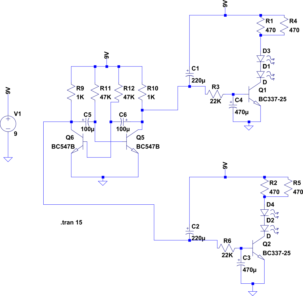
Schematic from the LTSpice simulation.
After running the simulation and tinkering with the component sizing, the timing seemed reasonable for a slow but steadily frightening atom blinking sequence.
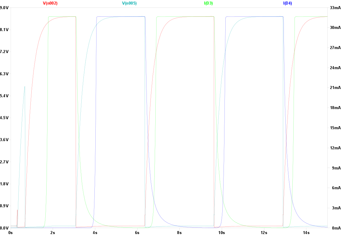
Signal plot of the simulation. Oscillator outputs in red and turquoise. Diode currents in green and blue.
Now you might ask, why in the hell did that guy use two resistors in parallel? Easy answer: I forgot to design for two LEDs in series and already had soldered the two 470 resistors, so I botched up a second in parallel to get the current up to desired LED brightness.
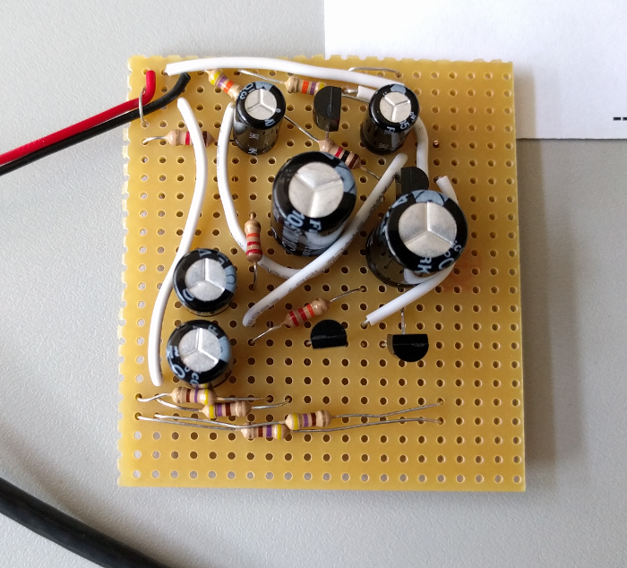
Put together on a prototype board. Such beautiful placement!
After prototyping everything was assembled on a board with the famous place first then think about routing algorithm. What was missing was the case and the LEDs, of which the top part can be seen in the next image.
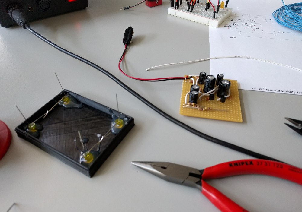
Finished board and 3D printed case top.
Putting it all together, I realized that those bloody 9V blocks are bulkier than anticipated. Therefore, the ugly wire outside ... something to learn for next time.
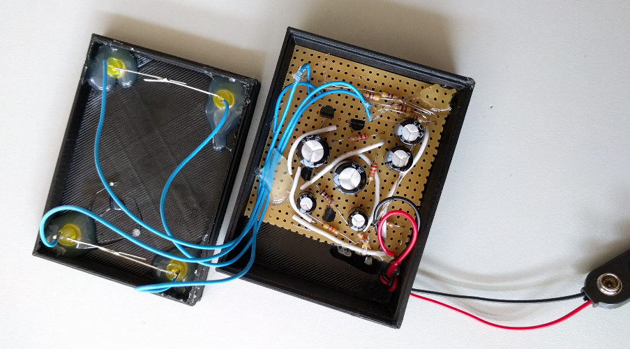
Finished board and top. Make sure to use lots of hotglue. This shows quality engineering work.
Look at the final product, intimidating, isn't it? No?
Blinker in action.
Download the LTSpice simulation file here.