Onkyo TX-SR313 Repair
Disclaimer: I do not advise you to try repairing any equipment connected to mains power on your own if you have no clue. Especially, while it is connected to the mains power. Proceed at your own risk. Remember: I told you do not even think of opening up that receiver case!
I have my Onkyo TX-SR313 since a few years now and it is a very nice piece of amplifier equipment. The sound quality is really superb and it has all the connections and functionalities I need. Unfortunately, when watching some of my favourite series, in the midst of an action scene, suddenly, the receiver shut off. First, I suspected some overheating issue or similar, so I continued watching with my crappy built-in TV speakers, but then after a while the amplifier would not turn on. This is when I started worrying (in reality, I already worried before, since it had never overheated before, even on high volumes and there is nothing blocking the airflow above it, so this should not be an issue).
Even on the next day (because a lot of guides on the net suggest letting it cool down and decharge all the caps and such), the thing would not work. The only indication of life it was giving was a constant glowing "HDMI Thru". When I pressed the power button, nothing would happen, except the "HDMI Thru" led would start blinking. No satisfyingly clicking relais inside, nothing.
Apparently, the most common fault in receiver amplifiers with dedicated transistors in the amp is such a transistor shorting out. This can be due to overheating or more likely due to a faulty bias current resistor. These resistors are the white blocks in front of each transistor pair. Therefore, I went ahead and checked every resistor if it has the correct value and every transistor if it was shortened out from collector to emitter. For further details, I would like to refer to the many excellent youtube videos out there.
Every resistor and every transistor checked out positively and by visual inspection of the rest of the device, I could not find any obvious broken components (for example bulged up capacitors or something like that). At first, I was tempted to give up, since a quick research could not bring up any other obvious things to check or obvious faults in similar devices, that would exhibit the same behaviour.
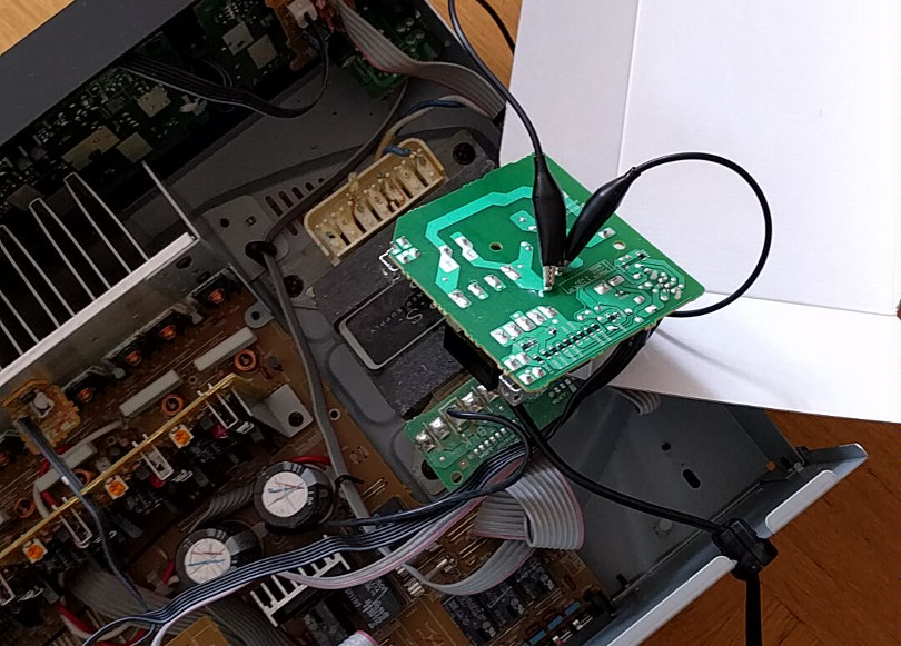
But then taken by my ambition I decided to repair that sucker. I downloaded the schematics and started looking through it. Especially through the amplifier section, since I still suspected some protective circuit to shut down the device immediately. After a while of studying and more youtube videos about receiver repairs, I encountered one specific video by the excellet EEVBlog, where a broken Yamaha receiver gets fixed, which has a fault in the standby power supply circuit. This gave me the idea to look more specifically at this section and check out the voltages there.
If you look at this part of the schematic, it is clear that a 12V support voltage is generated which is supplied to the main IC and then two more interesting lines come back, which are those which trigger the main supply relais. Especially, POWERD.
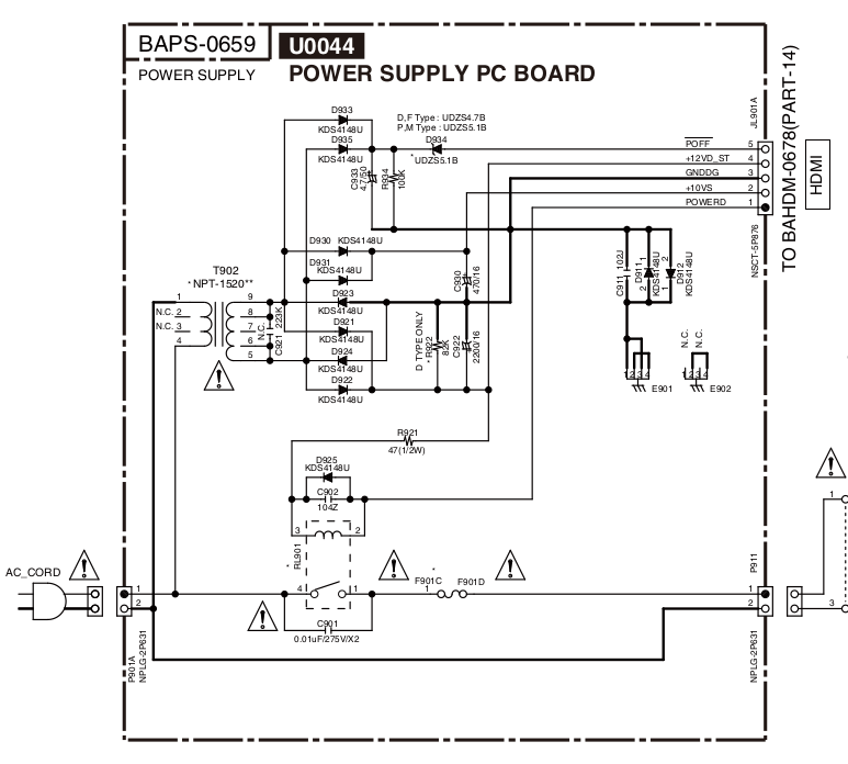
Schematic for the power supply section.
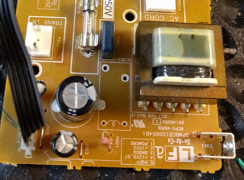
So it ocurred to me to check out the relais in the first place, since if there is still some protective circuit engaged, the relais should be triggered at least once and then immediately release again when the power button is pressed (which it did not!).
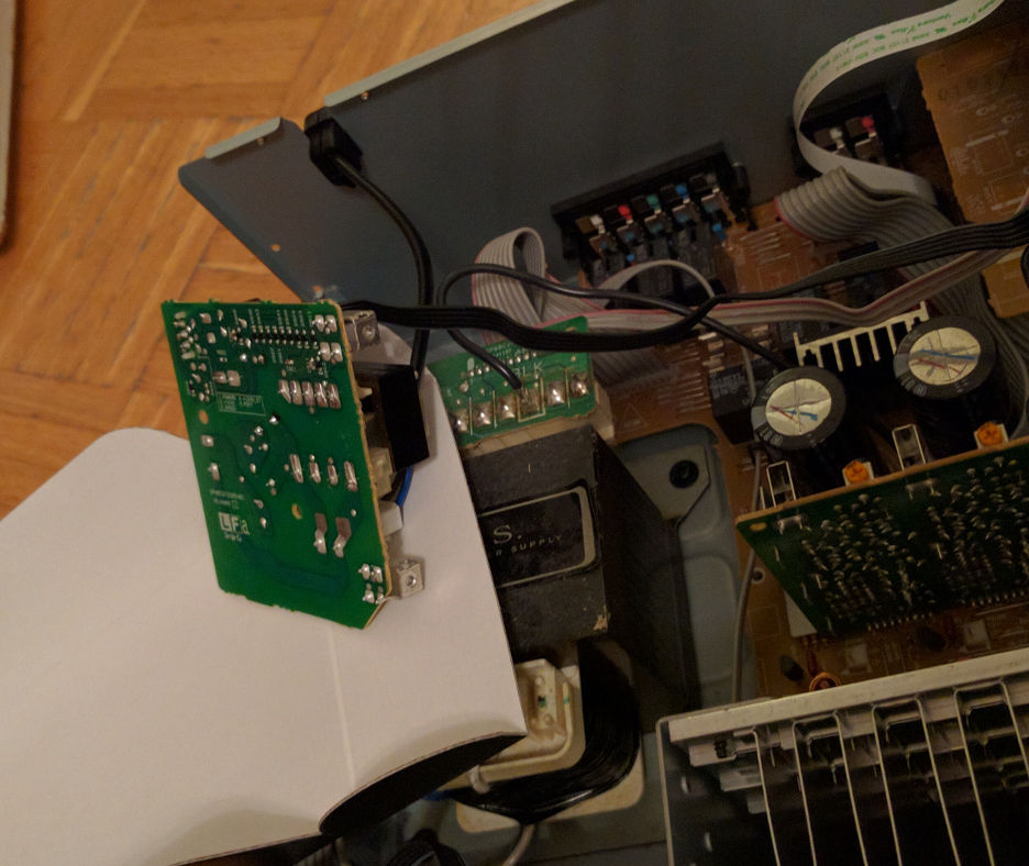
So supplying 12V to the lines +12VD_ST and GND to POWERD did not produce any clicking sound. Very odd. Could it be the relais itself is broken? A quick bridging of the relais ...
Dangerously bridged relais makes it work.
revealed, that indeed the relais is broken. The reveiver turned on and did it's job flawlessly. So now we know who is to blame.
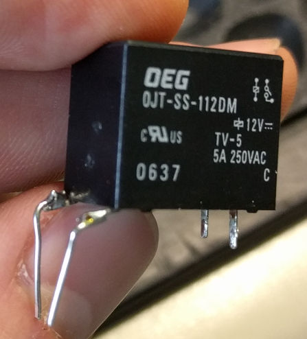
A quick search brought up that the type of relais Tyco is more or less not available to the end user for buying. Therefore, a suitable replacement had to be found. The datasheet of the Tyco SDT-S-109LMR2 relais revealed, that it is a relais designed for 9V operation and the coil is supposed to have 540 Ohms with a max coil power of 150 mW. Good luck finding exactly a matching piece.
Digging around further in the schematics, reveals that the relais is driven by a KRC105S transistor, which is rated up to 100 mA, so we should aim for maximum coil current of 50 mA, just to be safe.
Fortunately, I could find in an old stack of discarded PC power supplies one which not only has 230 V input but also a switched 230 V output for a monitor or such (thumbs up for that old things lying around). It had a relais in, which pretty much matched the requirements.
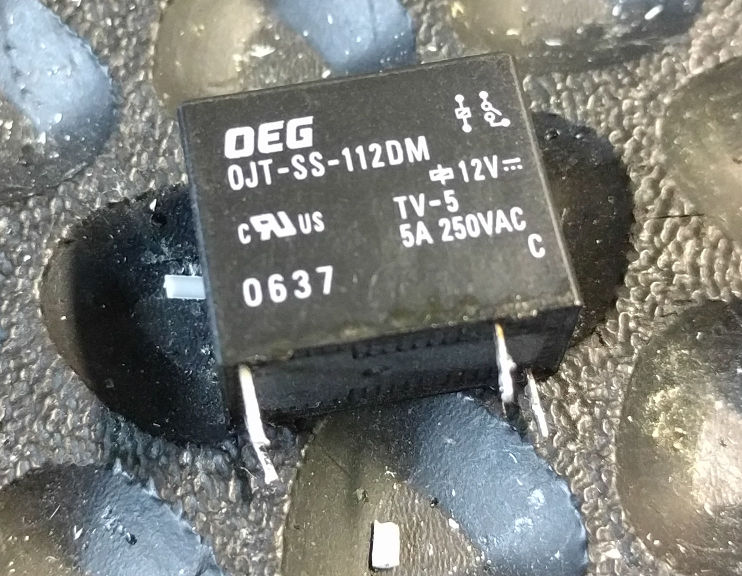
Replacement Relais.
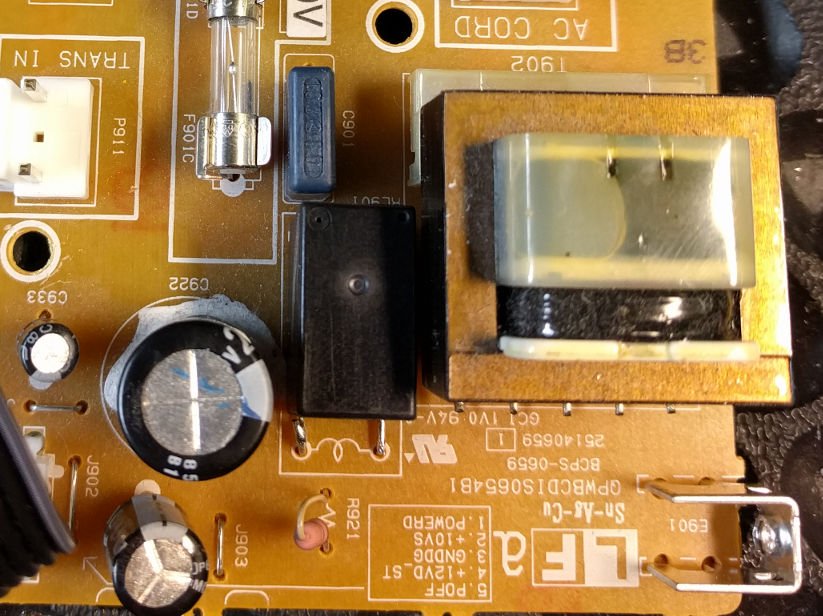
5 amps of switching at the 230 V side and a coil resistance of around 330 ohms. Almost perfect. Almost, because desoldering the old relais
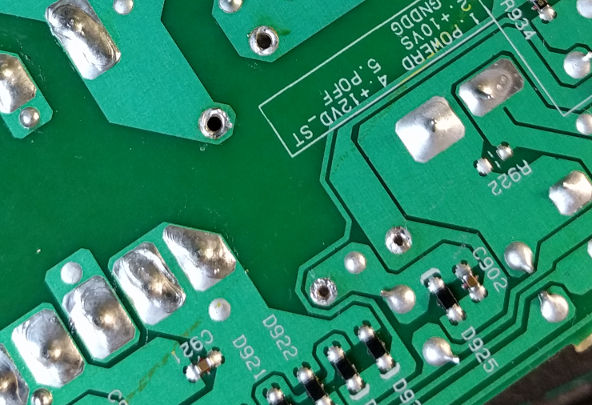
Desolder the old relais.
revealed, that the new one was too short to perfectly fit in there.
The new one is too short, bummer.
But a electronical engineer approved solution, helped to get the new component in place.
There - I fixed it!
No one will find out that is not original.
After testing the new relais, the machine was working perfectly again.
Done.